Shock and awe(some) vibration testing
 The CSIRO Fire Systems Laboratory announces the significant upgrade of its vibration test equipment. The laboratory has purchased and commissioned two new shaker and amplifier pairs, vastly extending its test capability and service offerings.
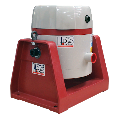
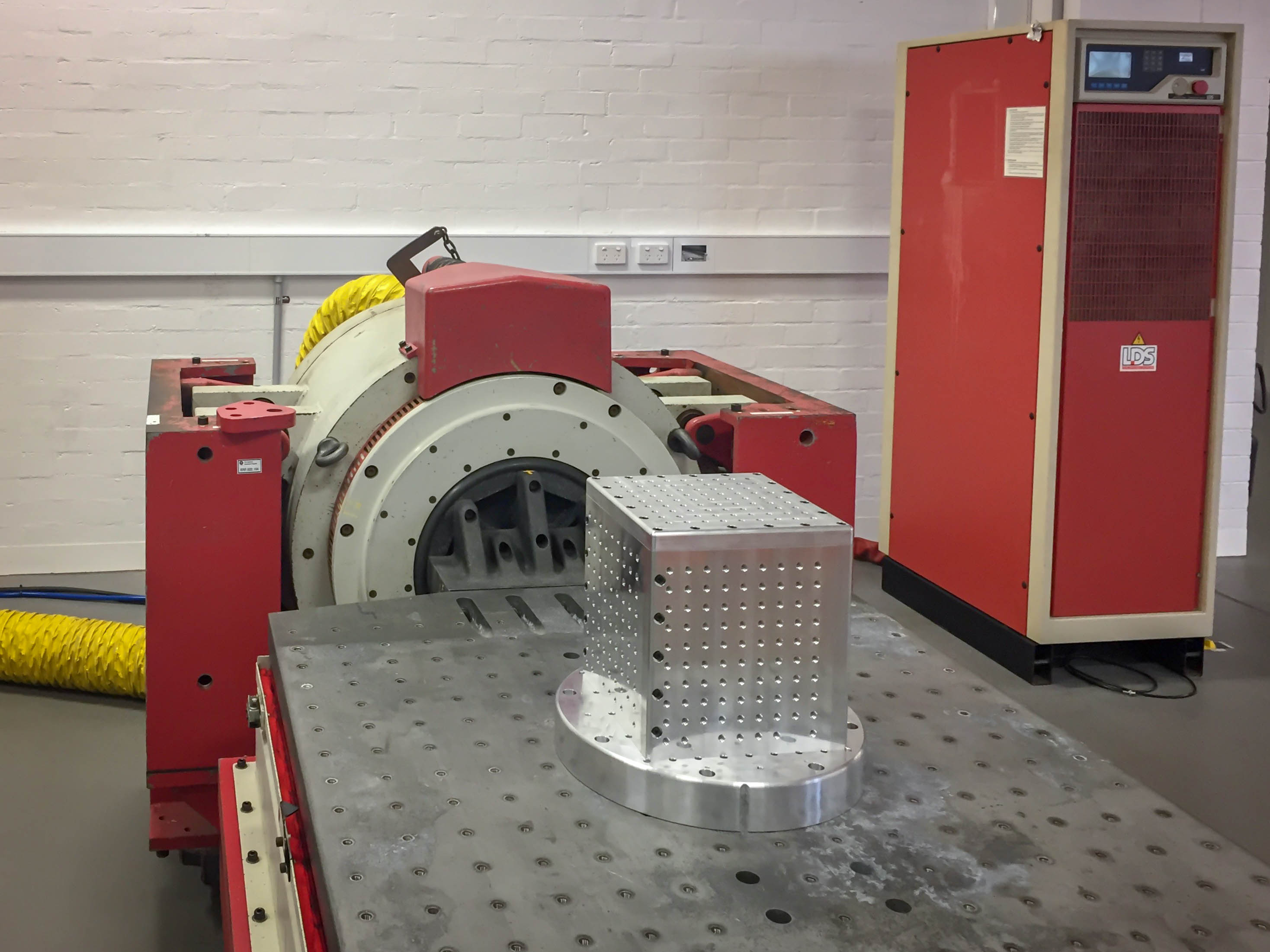
LDS V455 permanent magnet shaker on trunnion.
An LDS V824 Shaker/Slip Table Combo system was recently acquired and commissioned.
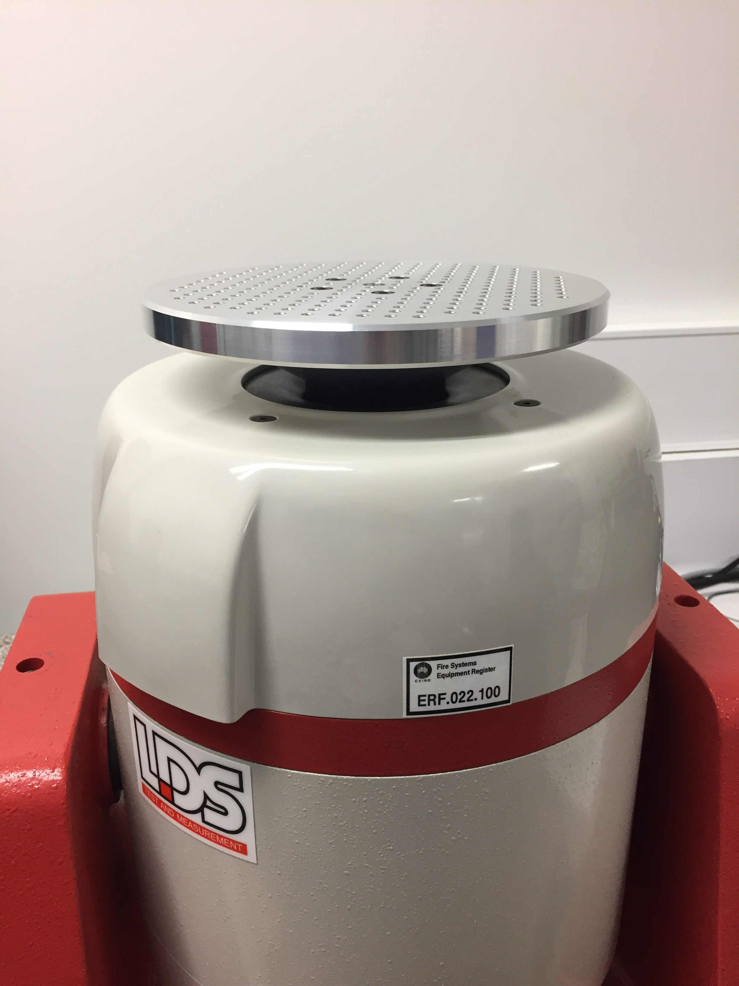
Additionally, a small LDS V455 permanent magnet shaker and PA1000L power amplifier was supplied by Brüel and Kjær to replace the venerable LDS V406 shaker and PA100 amplifier which has been used by the laboratory for many years. The V455 shaker and amplifier provides up to 0.5 kN (sinusoidal) or 0.7 kN (half-sine shock) force.

V824 shaker attached to slip taker in horizontal vibration orientation.
The V824 combo, weighing in at more than 4500 kg, is significantly larger in all ways. Driven by the matched LDS SPA32K power amplifier, the shaker can impart a sustained sinusoidal peak force of 26.7 kN (6000 lbf), and more than 40 kN shock force, over a peak-peak displacement of 25.4 mm. The SPA32K is rated for up to 32 kVA output into the shaker. The electrodynamic V824 is mounted on an pneumatically isolated trunnion (LDS LIN-E-AIR suspension) which also supports a 900 x 900 mm magnesium alloy slip table for horizontal test orientation. Due in no small part to its Defence heritage, the V824 combo system is equipped to support loads of up to 450 kg in the vertical orientation thanks to the pneumatic internal load support system. Horizontally, on the hydraulically-supported slip table which is guided by two precision hydrostatic linear bearings, test loads of up to 1000 kg may be supported.
All vibration and shock tests are controlled and monitored by a LDS Dactron LaserUSB Vibration Controller which provides connection for up to eight accelerometers as single or multiple/average control inputs. The controller and its software offers sinusoidal and random vibration excitation methods with closed-loop control, and a range of classical shock pulse shapes including half-sine, terminal peak sawtooth, and trapezoidal. The laboratory typically uses Brüel and Kjær Type 4507 constant-current line drive (CCLD) piezo accelerometers for acceleration measurement.
 The Fire System Laboratory currently undertakes, and is NATA accredited for vibration testing in accordance with AS (IEC) 60068.2.6. Tests are typically conducted on small fire detection and alarm system equipment, such as residential smoke alarms, smoke and heat detectors, loudspeakers, or I/O modules etc. Broad-band random tests in accordance with AS (IEC) 60068.2.64 or other similar methods are also able to be performed.
The upscaled equipment now adds the capability for the laboratory to undertake vibration testing on large equipment including control and indicating equipment and power supplies (“fire control panels” or “FDCIE”) complying with AS 7240.2/4, and emergency warning and evacuation control systems (“EWCIE” or “EWIS panels”) complying with AS 4428.16.
 The laboratory’s capability now also includes the provision for vibration tests on vehicular fire suppression systems in accordance with AS 5062. This heavy-vehicle protection Standard requires a very challenging vibration test of a constant 5 g acceleration across a frequency range of 10 to 150 Hz. At the low frequency limit, this requires the entire suppression system to be traversed back and forward across a distance of 24.8 mm ten times a second! In fact, the very same V824 combo system, or another identical shaker system, has been used to conduct vibration tests on many of the vehicular systems that are certified by CSIRO’s ActivFire Certification Scheme to AS 5062.
Notably, the new equipment also provides the capability for the laboratory to conduct Shock tests in accordance with AS (IEC) 60068.2.27. This is the generic shock test method required to be applied to fire detection and related equipment by the relevant parts of the AS (ISO) 7240 and EN54 series. For example, field I/O modules, which are required by AS 1670.1 to comply with AS ISO 7240.18, are subject to a series of 6 ms half-sine shock tests scaled in amplitude (acceleration) to their mass. The maximum peak shock amplitude that is applied to such equipment is 102 g, decreasing according to the formula of 10 x (100 – 20 x M) (m/s2) where M is the test item mass in kilograms (kg).
While the CSIRO Fire Systems Laboratory has traditionally focussed on the testing of fire detection systems and related products, the shock and vibration capability and equipment is applicable to all product categories, including those intended for aerospace and aeronautics, maritime, rolling stock (rail) and defence applications. Relevant product test standards for these types of equipment include DOD MIL-STD-810G, MIL-STD-167, and RTCA DO-160.
The Fire Systems Laboratory is located within the extensive CSIRO Clayton campus in Victoria, Australia. The laboratory is co-located on the campus with the CSIRO Consolidated Engineering Facility (CCEF) which provides leading engineering design and manufacturing. The CCEF is available to the laboratory to assist in the setup and design of shock and vibration test fixtures and items. The CCEF collaborates with the laboratory to provide various test fixtures milled from suitable alloy plates for the mounting of test items.
|
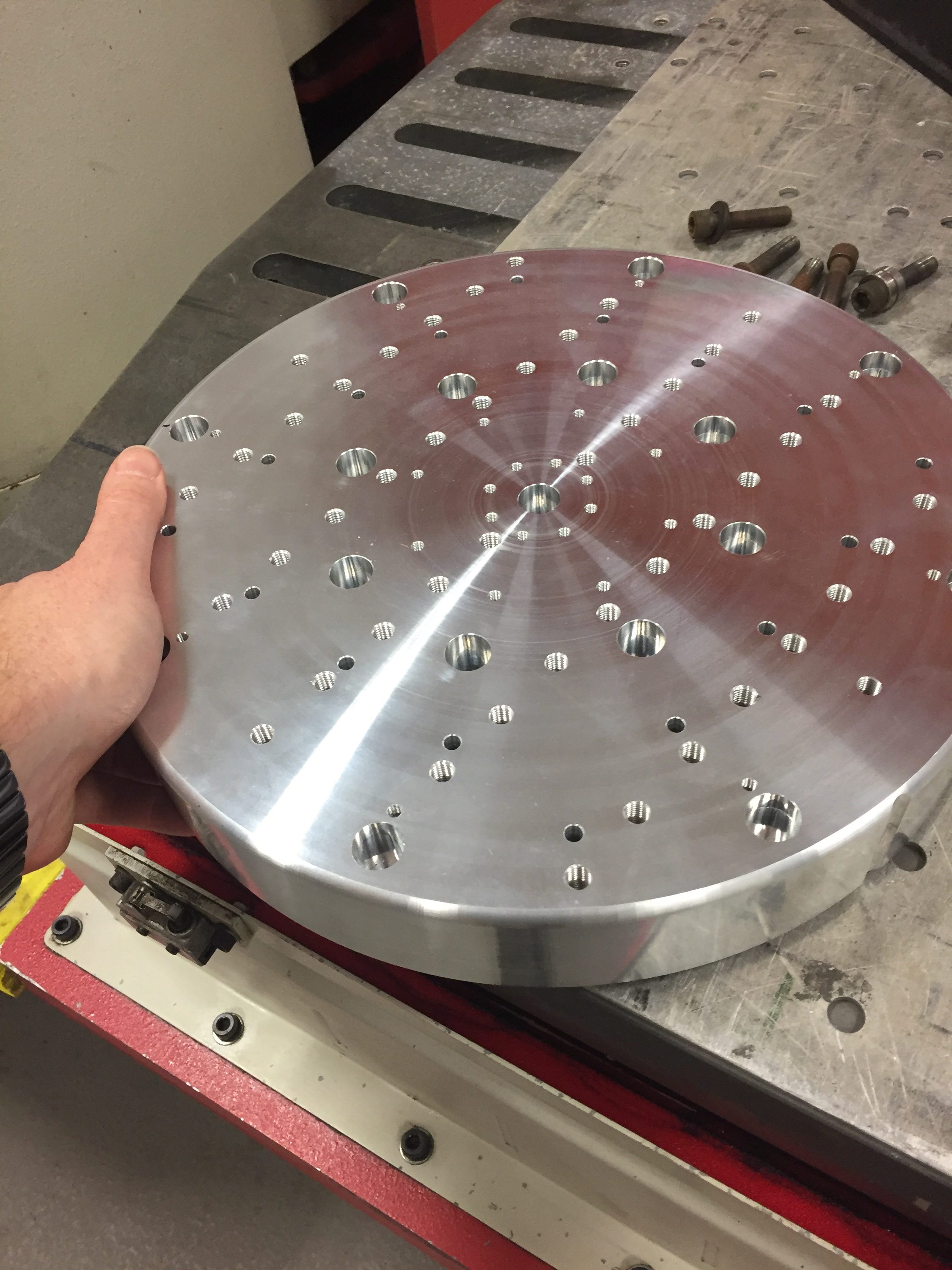
Test item mounting fixture being milled at the CCEF from aluminium plate. |
Finished circular mounting fixture prior to assembly on shaker. |
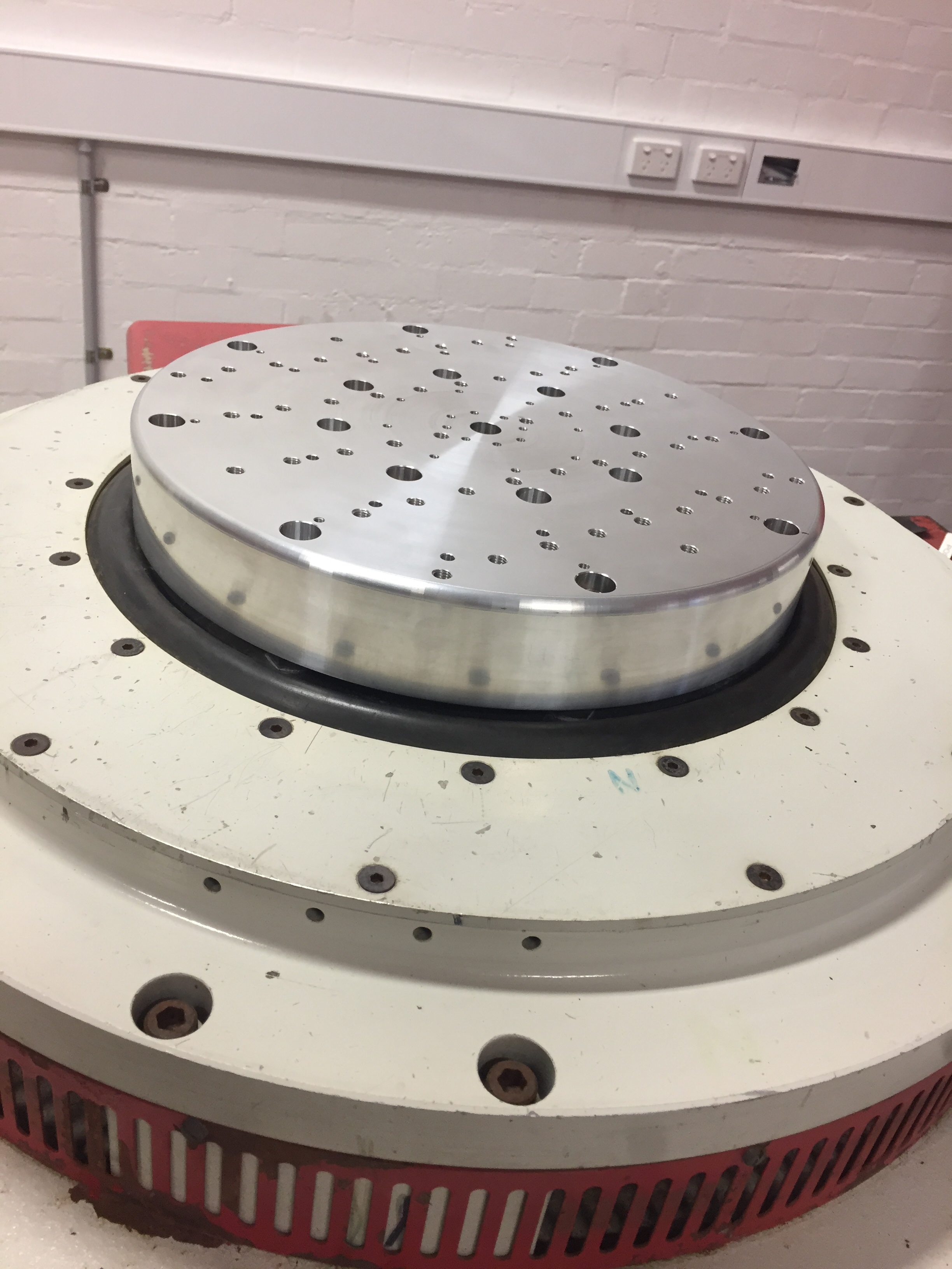
Fixture mounted to V824 shaker in vertical orientation. |
V455 head expander milled from 200 mm aluminium alloy round stock |
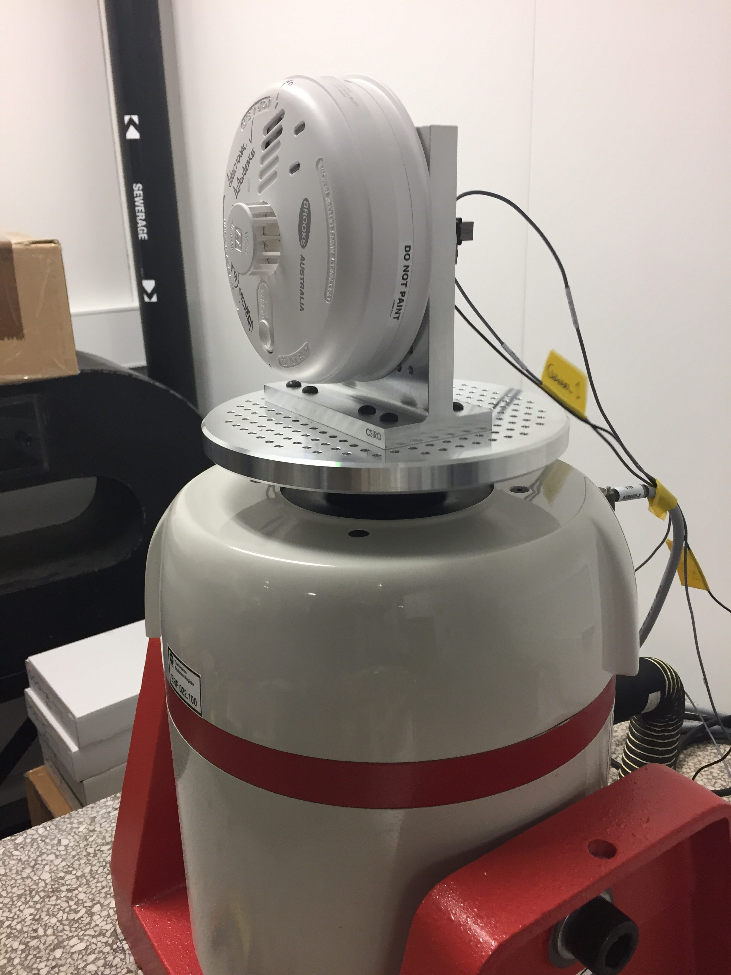
V455 shaker with head expander fitted with additional machined fixture. Test item attached for vibration testing. |
|
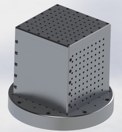
CAD mode rendering of cubic test fixture for attachment to circular plate fixture on V824, prior to manufacturing. |
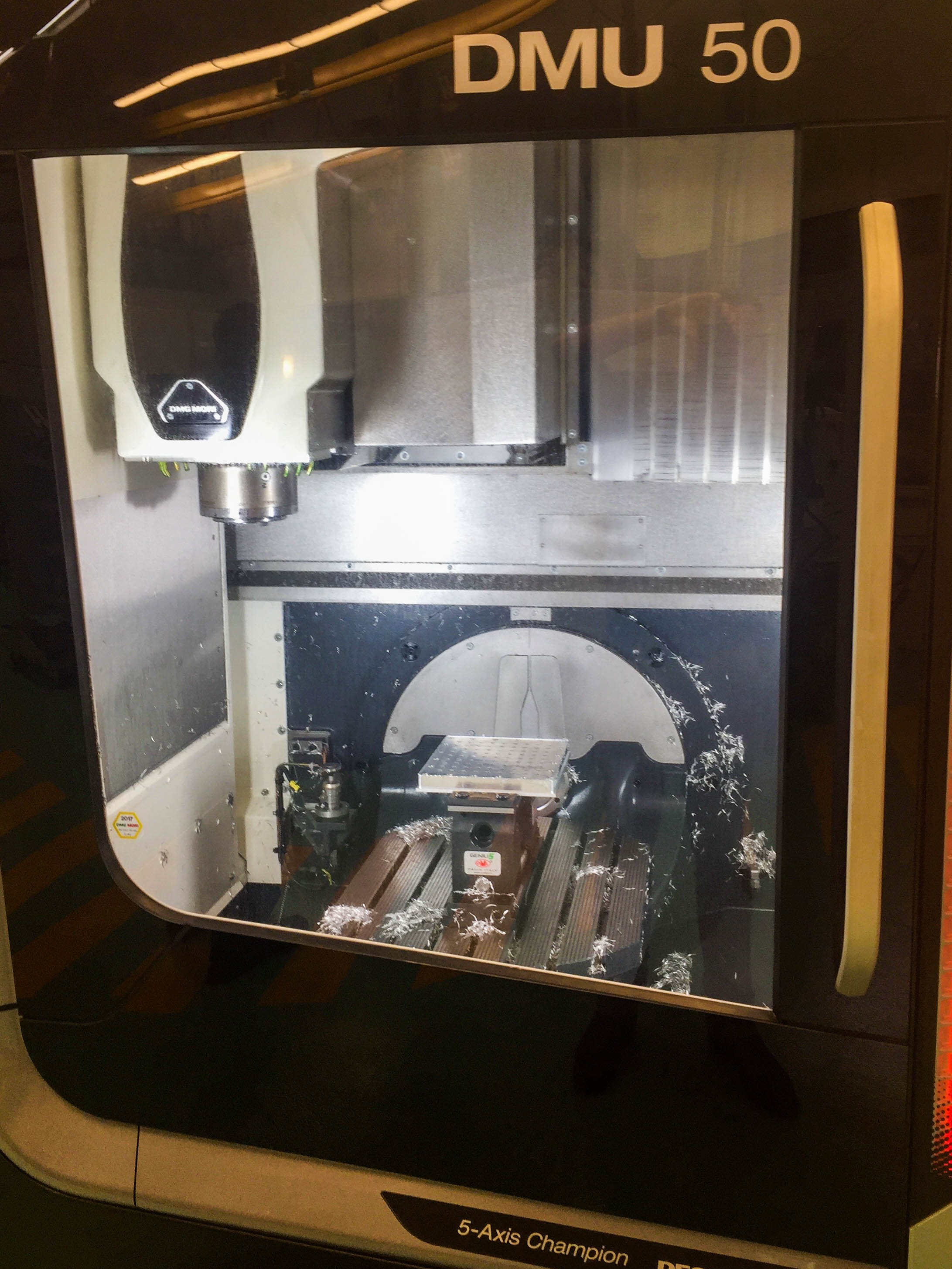
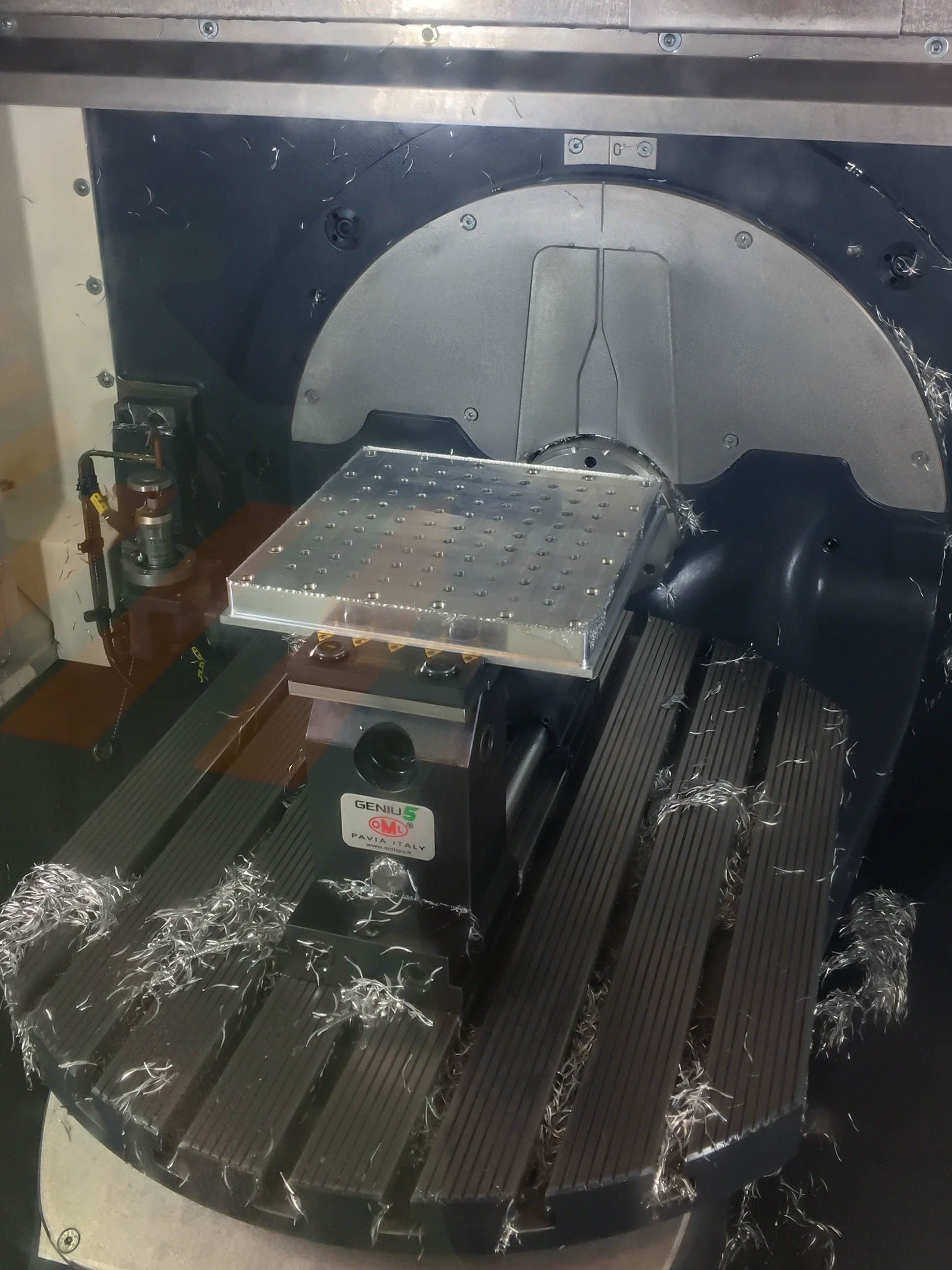
Face of cubic test fixture during production on CCEF 5-axis CNC mill. |
Face of cubic test fixture during production on CCEF 5-axis CNC mill. |
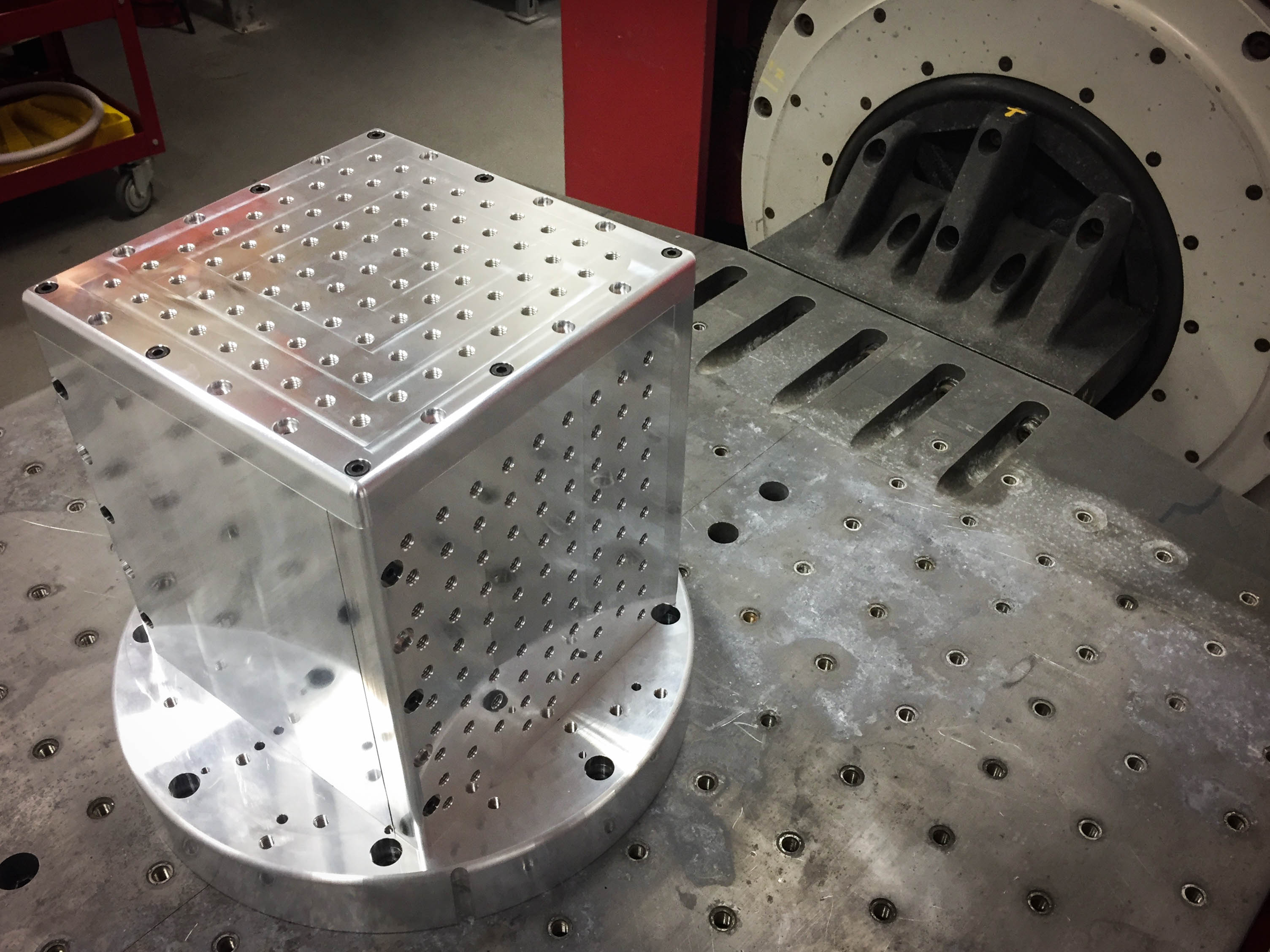
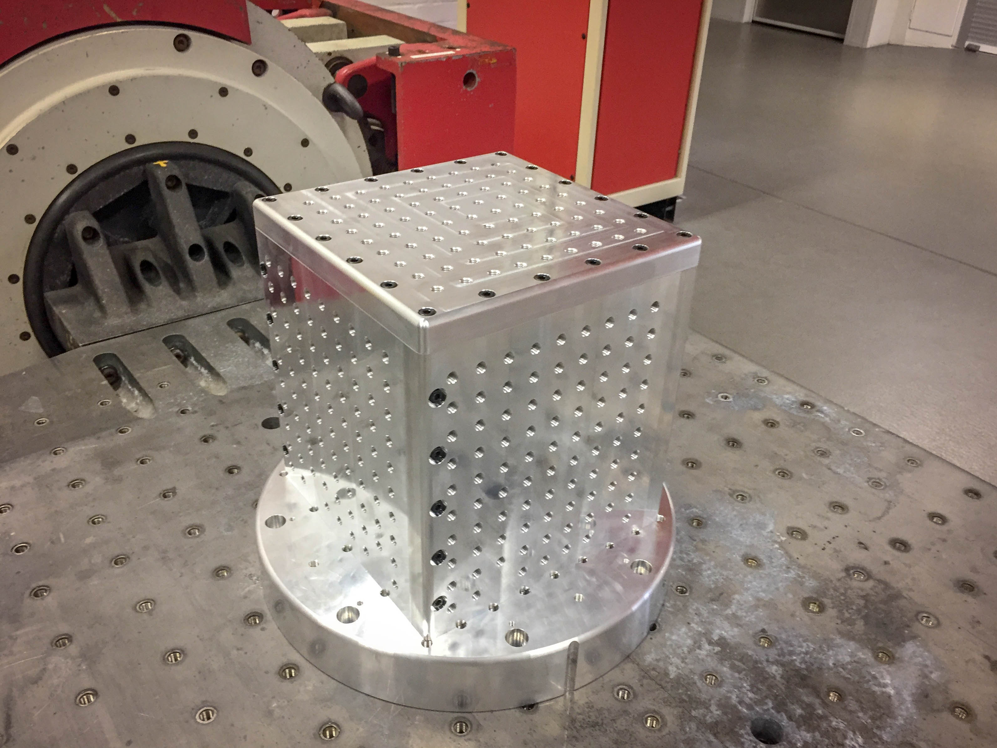
Al alloy cubic test fixture completed by CCEF. |
Cubic test fixture on slip plate. Fixture may be mounted directly to shaker or to slip table to provide various test orientations. |

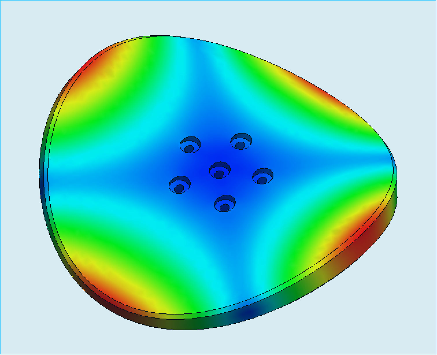
To validate the design of mounting fixtures, the laboratory, in conjunction with the CCEF, performs Finite Element Analysis (FEA) on CAD models of each item. The results of the FEA predict the vibration modes (deformational shapes) expected of a specified design, and their natural frequency. The FEA takes as input the design geometry, as well as all of the relevant material properties such as density and elastic modulus (stiffness), as well as fixing and loading details.
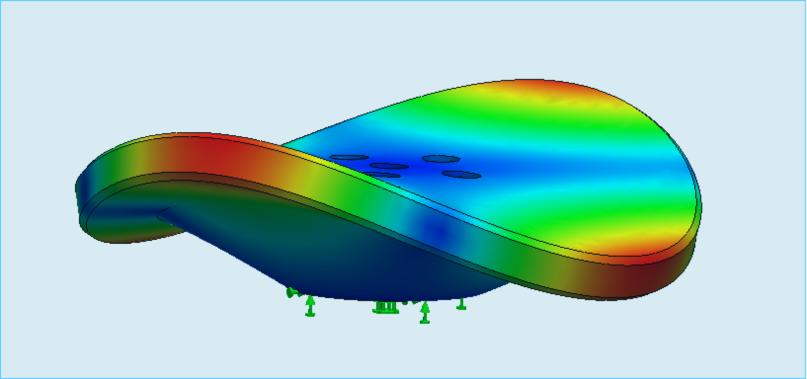
FEA prediction of Mode 4 of V455 head expander at approx. 3000 Hz. Extent of deformation is exaggerated for illustrative purposes.
The main purpose of the FEA is to guide the design to a geometry whose lowest resonant (natural) frequency will be outside (typically above) the expected test frequency range. For example, fire detection equipment is subject to sinusoidal frequency sweeps, according to AS 7240/EN 54, up to a maximum frequency of 150 Hz.
The FEA outputs deformed 3D models demonstrating the shape and extent of each vibration mode, and its associated frequency. By undertaking cycles of design and analysis, the geometry can be refined to optimise usable shape, lowest mass, and highest frequency. Additionally, the effects of using different construction materials can be trialled, as libraries of physical properties are readily available for all common materials such as various Aluminium and Magnesium alloys.
Enquiries related to vibration testing of any product type may be directed to Dr. Christopher Preston, Team Leader – Fire Systems Laboratory, (christopher.preston@csiro.au).