NovaSAR-1 User Guide
This User Guide provides a description of the NovaSAR-1 specifications, modes and products. It also gives information on the calibration, orbit characteristics and compatible software. If you cannot find the information you are looking for please contact us
Navigation
Use the following links to navigate your way around the User Guide:
- Overview A brief description of the mission and SAR technology
- Satellite Specifications Defines the main mission characteristics
- S-Band SAR Provides information on S-band and comparisons to X, C and L-Band
- Automatic Identification System (AIS) Describes the AIS secondary payload
- Baseline Acquisition Modes Describes the high-level NovaSAR-1 acquisition modes: Stripmap, ScanSAR, ScanSAR Wide and Maritime
- Detailed Acquisition Modes Defines the further options available within the baseline modes in more detail
- Imaging Characteristics This section has information on polarisations, pass direction and antenna pointing
- Revisit and Coverage Provides details on the NovaSAR-1 orbit characteristics, revisit and coverage
- Product Types and Processing Levels Describes the processing levels in which NovaSAR-1 products are provided
- Naming Conventions Describes the data naming conventions used for NovaSAR-1 product folders and files
- Data Formats and File Types Describes the data formats that NovaSAR-1 products are distributed in
- Data Quality Information on features such as ambiguities, speckle and geolocation accuracy
- Calibration and Validation Outlines the procedures used in the calibration of NovaSAR-1 data
- Compatible Software Lists the software programs with readers available for processing NovaSAR-1 data
NovaSAR-1 is a joint technology demonstration initiative of SSTL (UK) and Airbus DS (former EADS Astrium Ltd, Stevenage, UK), funded by the UK Government via the UKSA (UK Space Agency). The overall objective is to make SAR (Synthetic Aperture RADAR) observation missions more affordable to a customer base and to open up new applications in the S-band microwave region of the electromagnetic spectrum.
NovaSAR-1 is a much smaller version of traditional spaceborne SAR sensors, with a mass of 450 kg. It was developed to be low-cost whilst still providing medium resolution data with wide coverage. This is achieved by:
- Reuse of heritage avionics (satellite platform) based upon the SSTL 300 avionics (used for Nigeriasat-2) to reduce risk.
- Compatibility with existing SSTL satellite ground control segment.
- The payload back-end comes from the existing Airbus Defence and Space UK instrument architecture.
- Use of COTS technology where suitable to reduce cost.
The SAR payload operates in the S-band microwave frequency (3.2 GHz), corresponding to a 9.4 cm wavelength and can operate in four operational modes. The spacecraft is also equipped with a secondary Automatic Identification System (AIS) payload produced by Honeywell Aerospace that can be combined with NovaSAR-1’s maritime surveillance mode for ship identification.
Watch this video from SSTL to learn more about NovaSAR-1
What are the benefits of RADAR imaging?
Radio Detection and Ranging (RADAR) is an active imaging technology in which pulses of microwave energy are emitted from an antenna and the resulting reflections are used to create images. Some advantages over optical imaging include:
-
- The ability to image day and night as the active SAR system does not rely on sunlight.
- The signal can penetrate clouds, rain, dust and even volcanic ash, providing imagery where traditional optical imagery would fail.
- Depending on the signal wavelength, SAR can image through the vegetation canopy.
- The lens is not fixed therefore the sensor is flexible regarding resolution and ground coverage.
What is Synthetic Aperture RADAR?
Synthetic Aperture RADAR (SAR) uses the different locations of the sensor, as it moves along the flight path, to simulate a large antenna from a smaller one. This enables SAR sensors to provide high-resolution imagery that does not degrade with distance like traditional RADAR systems with large antennas.
For detailed information on SAR visit our Resources page
The NovaSAR-1 satellite has the following mission characteristics:
| Parameter | Value |
| Imaging frequency band | 3.1-3.3GHz (S-band) |
| Antenna | Microstrip patch phased array (3m x 1m) |
| No. of phase centres | 18 |
| Peak RF power | 1.8kW |
| Polarisations | HH, HV, VH, VV |
| Design life | 7 years |
| Mass | 450kg |
| Orbit | 583km SSO 1030am LTAN |
| Propulsion system | Xenon-based |
| Payload duty cycle | 2 min per orbit |
| Payload data memory | Up to 256 GBytes |
| Downlink rate | 400 Mbps |
| Downlink frequency band | X-band (8.025-8.4 GHz) |
| TTC frequency band | S-band (2025-2110 MHz, 2200-2290 MHz) |
| Geolocation | <50 metres |
The NovaSAR-1 SAR payload uses the S-Band frequency range, which is less common in spaceborne SAR systems than the X-, C-or L-bands.
S-Band SAR imaging has already proven utility onboard the Russian Kondor-E1 (2013) and Almaz-1 (1991) satellites and the Chinese HJ-1C (2012) satellite. It is the selection of S-Band that makes NovaSAR-1 possible, as the efficiency of the new Gallium Nitride amplifier technology offers higher conversion of energy to radio-frequency and produces far less surplus heat than those amplifiers currently used for X-, C- and L-Band satellites.
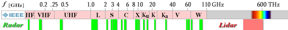
RADAR and LIDAR frequencies. Source: IEEE
Some differences that NovaSAR-1 S-band imagery may offer compared to other SAR frequencies:
- Less sensitive rain shadowing, which has been shown to be a problem at X-band.
- Better ground penetration than higher frequency C- and X-bands – potentially useful for detection of variations in soil moisture and detection of sub-surface features.
- Shows discrimination between different vegetation structural types, due to greater penetration through the upper canopy layers, making it effective for vegetation monitoring, land cover classification, and forestry analysis.
- The effect of Faraday Rotation (i.e. the rotation of the polarisation vector of a radio wave propagating through the ionosphere which results in a reduction backscatter levels) is minimal using S-band compared with standard L-band sensors.
Comparison of SAR bands
| Frequency Band | Frequency Range | Wavelength (cm) | Example Spaceborne SAR Systems (past, present, planned) | Example Spaceborne SAR Systems (past, present, planned) |
|---|---|---|---|---|
| P-band | 43.2-438 MHz | 68.5-69.4 | BIOMASS | High penetration, detection of targets concealed by foliage or camouflage, buried object, archaeological, estimates of biomass, map forest disturbances. |
| L-band | 1215-1300 MHz | 23.1-24.7 | SEASAT, JERS-1, ALOS PALSAR, ALOS-2 PALSAR-2, SAOCOM-1A/1B, NISAR-L | Good penetration, land applications – forestry, environmental monitoring, agriculture, geology, hydrology. |
| S-band | 3.1-3.3 GHz | 9.1-9.7 | ALMAZ-1, HJ-1c, KONDOR-E, NovaSAR-1, NISAR-S |
Ship detection, ice mapping, oil spill detection, flood mapping, forestry mapping, crop classification. |
| C-band | 5.25-5.57 GHz | 5.4-5.7 | ERS-1/2, Envisat ASAR, Radarsat-1/2, RCM, Sentinel 1A/B | Sensitive to ocean features, ship detection, sea ice surveillance, oil spill monitoring, crop classification. |
| X-band | 9.5-9.8 GHz | 3.1-3.2 | TerraSAR-X/TanDEM-X, COSMO-SkyMed, IGS-1B/3B, TecSAR, RISAT-2, PAZ, KOMPSAT-5, SAR-Lupe | Sensitive to surface roughness, high-resolution applications, topographic mapping, flood mapping, early-stage crop growth. |
NovaSAR-1 is the first civilian SAR to have an AIS receiver on board at the same time. AIS is a Very High Frequency (VHF) system, designed for the automated location and tracking of vessels. AIS transceivers are fitted on international voyaging ships with a gross tonnage greater than 300 tons and all passenger ships. Messages report a minimum of:
- the vessel’s unique identifier
- speed
- direction
- heading
These messages are transmitted at least every 30 seconds for ships in motion (up to every 2 seconds for fast-moving or manoeuvring vessels) and no less than every 3 minutes for ships at anchor. The AIS receiver onboard the NovaSAR-1 platform can be used to collect data just before and after the SAR imagery of the same area, providing additional information on the identification of detected ships and highlighting non-AIS transmitting vessels.
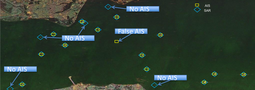
Image showing ships detected with SAR and AIS and how this can monitor suspicious activity. Source: SSTL
Image showing ships detected with SAR and AIS and how this can monitor suspicious activity. Source: SSTL
The AIS receivers are the next generation receiver from Honeywell and are a Direct Radio Frequency Sampling (DRFS) type with support for two antenna interfaces sampled by high-performance A/D converters and clocked by a low-noise https://aerospace.honeywell.com/high-stability clock. The receiver supports 6 AIS channels that include:
• Channels 1 and 2 (161.975MHz and 162.025MHz) are the currently operational AIS channels
• Channels 3 and 4 (156.775MHz and 156.825MHz) that have recently been allocated to space-based AIS
• Channels 5 and 6 (161.950MHz and 162.000MHz)
Each AIS receiver has 2 orthogonally mounted antennas that provide near omnidirectional coverage that will provide instantaneous coverage of approximately 20 million km².
As the AIS receivers are the secondary payload on the satellite the SAR data takes priority and as such we cannot target the AIS acquisitions. AIS collections are made for an average of 15 hours a day. To access the NovaSAR-1 AIS data please contact us.
For technical information on the Honeywell AIS-MS03 Receiver:
AIS Product Format
The AIS receivers will be operated in a cold redundant manner. Both AIS receivers’ output data in CCSDS packets that contain AIS packets as defined by the ITU-R-M.1371 standard. They will provide de-stuffed AIS packets with the removal of the preamble, start flag, checksum, end flag and buffer. As part of the standard operation of the receiver, any packets without a valid checksum are discarded.
- .ais – as downloaded binary with a CCSDS timestamped header appended to each demodulated AIS message
- .xml – AIS messages in NMEA-0183 text format
NovaSAR-1 offers a range of imaging modes with a variety of swath widths and imaging resolutions that can be chosen to best suit the needs of the user. All modes can be operated in either right-looking or left-looking antenna pointing directions and from an ascending (South to North) or descending (North to South) orbit.
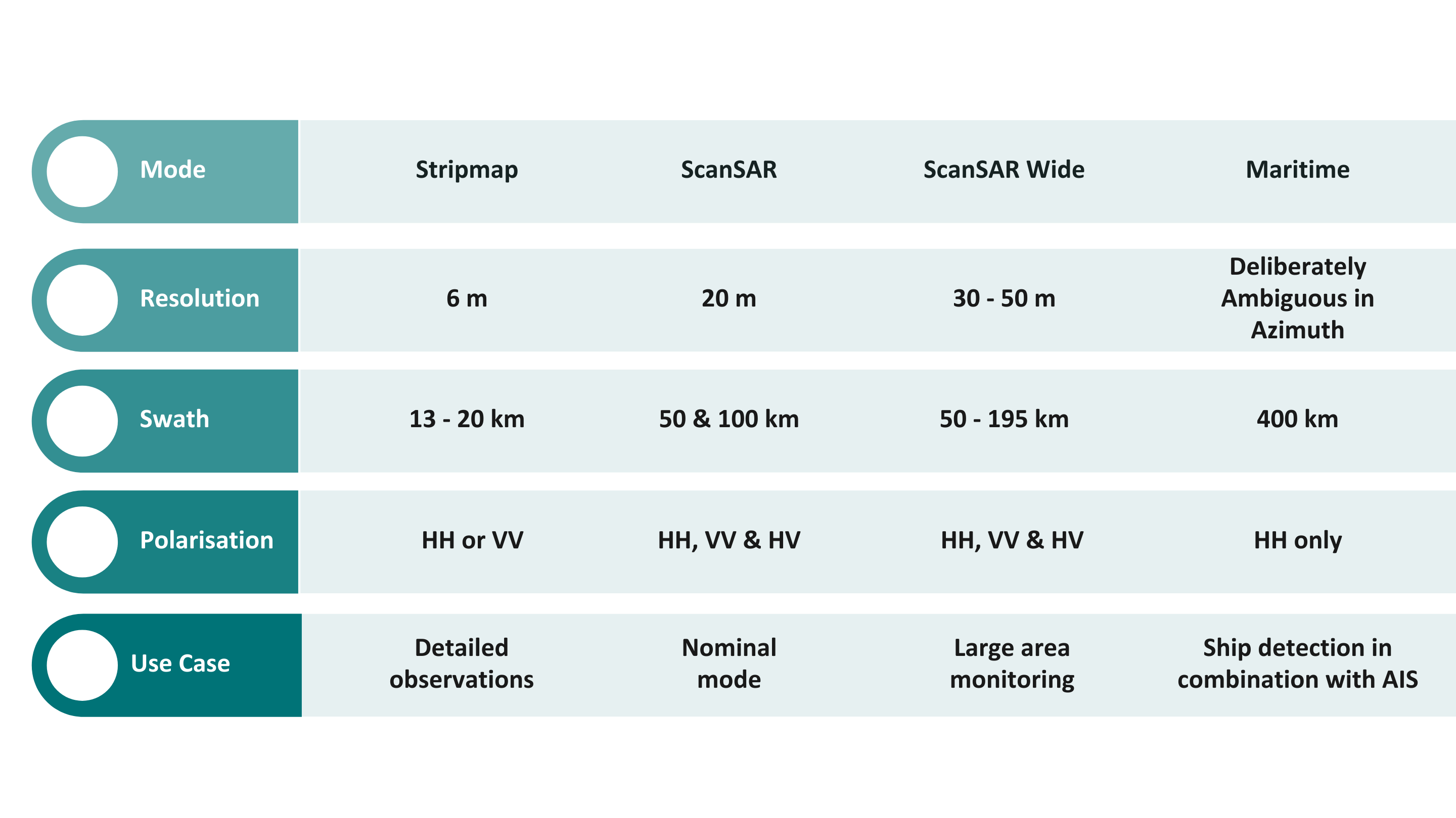
NovaSAR-1 Baseline Acquisition Modes and their characteristics
| ScanSAR – has a 20m resolution and up to 100km swath, this is expected to be the mode most commonly used for various target applications. Available in a variety of polarisations | ScanSAR Wide – extends the ScanSAR operations over a wider area of up to 190km, reducing the resolution to between 30 and 50m. Available in a variety of polarisations |
NovaSAR-1 modes shown in a single descending orbit with both Right and Left antenna pointing options shown.
| Stripmap – provides the highest resolution of 6 metres with up to 20km swath selected from a 150km field of regard, currently only available in single polarisations | Maritime – An innovative maritime ship detection mode for use in open ocean. HH polarisation with 30m resolution over an extended swath of >400km |
Within each of the baseline modes, except Maritime, there are a variety of mode options that vary according to ground range resolution, polarisation, incidence angles, swath width and the number of looks.
The modes we anticipate will be the most widely used, are defined in the table below:
| Mode type | Mode Name | Polarisation | Ground range resolution | Incidence angles (at 580km altitude) | No. of Swaths | Swath width (across track) | Worst Case Sensitivity (NESZ) | No. of looks | ||
| Maritime | Maritime | Single | Co | HH | 6m range, 13.7m azimuth | 34.5-57.3° | 1 | 400 km | <-9.7dB | 1 (1 range, 1 azimuth) |
| ScanSAR | 20m_ScanSAR_HHHV | Dual | CoCross | HH & HV | 20m | 12.95-31.18° | 8 | 25-27km | <-20 dB | 3 (1 range, 3 azimuth) |
| 20m_ScanSAR_HHVV | Dual | Co | HH & VV | 20m | 13.98-30.6° | 5 | 50-60 km | <-20.0 dB | 3 (3 range, 1 azimuth) |
|
| 30m_ScanSAR_VVHHHV | Triple | CoCross | HH & VV & HV | 30m | 15.0-29.1° | 3 | 50-56 km | <-27dB | 2 (1 range, 2 azimuth) |
|
| 35m_ScanSAR_100km_VVHHHV | Triple | CoCross | HH & VV & HV | 35m | 14.39-29.08° | 2 | 100 km | <-26 dB | 1 (1 range, 1 azimuth) |
|
| ScanSAR Wide | 33m_ScanSAR_195km_HH | Single | Co | HH | 33m | 11.82-30.26° | 1 | 195 km | < -19.5 dB | 3 (3 range, 1 azimuth) |
| 50m_ScanSAR_195km_HHHV | Dual | CoCross | HH & HV | 50m | 12.95-31.18° | 1 | 195 km | <-19 dB (HH) <-22 dB (HV) |
6 Co-pol (6 range, 1 Azimuth) 3 Cross-Pol (3 range, 1 azimuth) |
|
| Stripmap | 6m_Stripmap_HH | Single | Co | HH | 6m | 16-25.38° | 9 | 20 km | <-20 dB | 3 (1 range, 3 azimuth) |
| 21.29-31.2° | 11 | 13-20 km | <-19 dB | |||||||
| 6m_Stripmap_VV | Single | Co | VV | 6m | 16-25.38° | 9 | 20 km | <-20 dB | 3 (1 range, 3 azimuth) |
|
| 21.29-31.2° | 11 | 13-20 km | <-19 dB | |||||||
There are further modes on offer that are not expected to be as popular as those above. These modes are:
| Mode type | Mode Name | Polarisation | Ground range resolution | Incidence angles (at 580km altitude) | No. of Swaths | Swath width (across track) | Worst Case Sensitivity (NESZ) | No. of looks | ||
| ScanSAR | 20m_ScanSAR_HH | Single | Co | HH | 20m | 15.0-24.66° | 2 | 100 km | <-20.0 dB | 4 (2 range, 2 azimuth) |
| 24.51-28.94° | 50 km | <-21.0 dB | ||||||||
| 20m_ScanSAR_VV | Single | Co | VV | 20m | 15.0-24.66° | 2 | 100 km | <-20.0 dB | 4 (2 range, 2 azimuth) |
|
| 24.51-28.94° | 50 km | <-21.0 dB | ||||||||
| 30m_ScanSAR_HH | Single | Co | HH | 30m | 11.29-25.93° | 2 | 150 km | <-21 dB | 4 (2 range, 2 azimuth) |
|
| 27.35-32.01° | 55 km | <-19.5 dB | ||||||||
| 30m_ScanSAR_VV | Single | Co | VV | 30m | 11.29-25.93° | 2 | 150 km | <-21 dB | 4 (2 range, 2 azimuth) |
|
| 27.35-32.01° | 55 km | <-19.5 dB | ||||||||
| ScanSAR Wide | 40m_ScanSAR_195km_HV | Single | Cross | HV | 40m | 12.95-31.18° | 1 | 195km | < -23 dB | 4 (2 range, 2 azimuth) |
| 40m_CoCross_ScanSAR_Mid_HHHV | Dual | CoCross | HH & HV | 40m | 12.95-31.18° | 1 | 195km | <-21 dB | 4 Co-pol (4 range, 1 azimuth) 1 Cross pol |
|
| 45m_ScanSAR_195km_HHHV | Dual | CoCross | HH & HV | 45m | 12.95-31.18° | 1 | 195 km | < -26 dB | 1 (1 range, 1 azimuth) |
|
| 50m_Co6+Cross1_ScanSAR_195km_HHHV | Dual | CoCross | HH & HV | 50m | 12.95-31.18° | 1 | 195 km | <-19 dB (HH) <-27 dB (HV) |
6 Co-pol (6 range, 1 Azimuth) 1 Cross pol |
|
Notes:
- The number of range looks is the number of distinct or partially overlapping coherently processed looks extracted from the pulse bandwidth which are combined after detection to form the image.
- The number of azimuth looks is the number of distinct or overlapping coherently processed looks extracted from the Doppler spectrum which are combined after detection to form the image.
- The sensitivity of the SAR system is the ability to detect radar returns above the noise level of the system. The sensitivity is usually expressed by the Noise Equivalent Sigma Zero (NESZ or NEσ0) parameter. Conventional SAR modes are typically designed to provide a sensitivity value of at least -18 dB, corresponding to a low noise image.
Polarisations
SAR systems can control the polarisation of the microwaves that are transmitted and received by the sensor. Features on the ground appear differently depending on which transmit and receive polarisations are used.
Multi-polarised RADARSAT-2 images. 1) HH 2) HV 3) VV. Source: MacDonald, Dettwiler and Associates Ltd.
The NovaSAR-1 payload transmits both Horizontal (H) and Vertical (V) polarisations and can be operated in any of the four standard single polarimetric configurations:
- HH – for horizontal transmit and horizontal receive
- VV – for vertical transmit and vertical receive
- HV – for horizontal transmit and vertical receive
- VH – for vertical transmit and horizontal receive
The NovaSAR-1 payload receives one polarisation (H or V) at a time and switches between them for multi-polar modes. The instrument is therefore capable of providing incoherent, i.e. not exactly simultaneously, dual and tri polarisation. This alternating polarisation was also utilised on ESA’s Envisat.
HH and VV are commonly referred to as co-polarisation (or like-polarisation) backscatter components, while cross-polarisation connotes HV and VH. Note: whilst NovaSAR-1 has the functionality to operate VH, it is not currently configured in any imaging modes, all cross-polarisation modes use HV.
The ScanSAR and ScanSAR Wide modes have a variety of polarisations available. Stripmap is currently available in single polarisation HH or VV only and Maritime mode only functions in HH.
Pass Direction
NovaSAR-1 can image in both ascending and descending orbits.
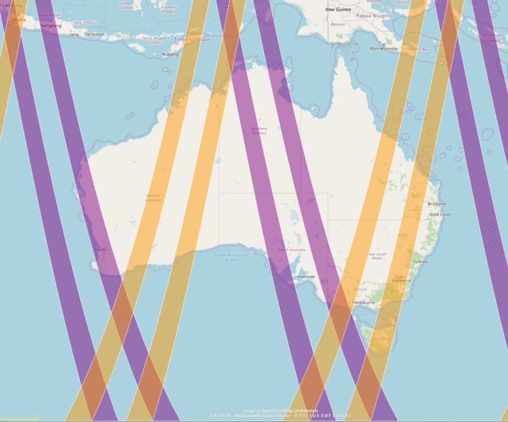
Pass Direction
NovaSAR-1 pass directions demonstrated with ScanSAR wide 195km swath: Ascending = Purple, Descending = Orange
Antenna Pointing
NovaSAR-1 does not image at Nadir but can image with either left or right pointing of the antenna (also referred to as the look direction).
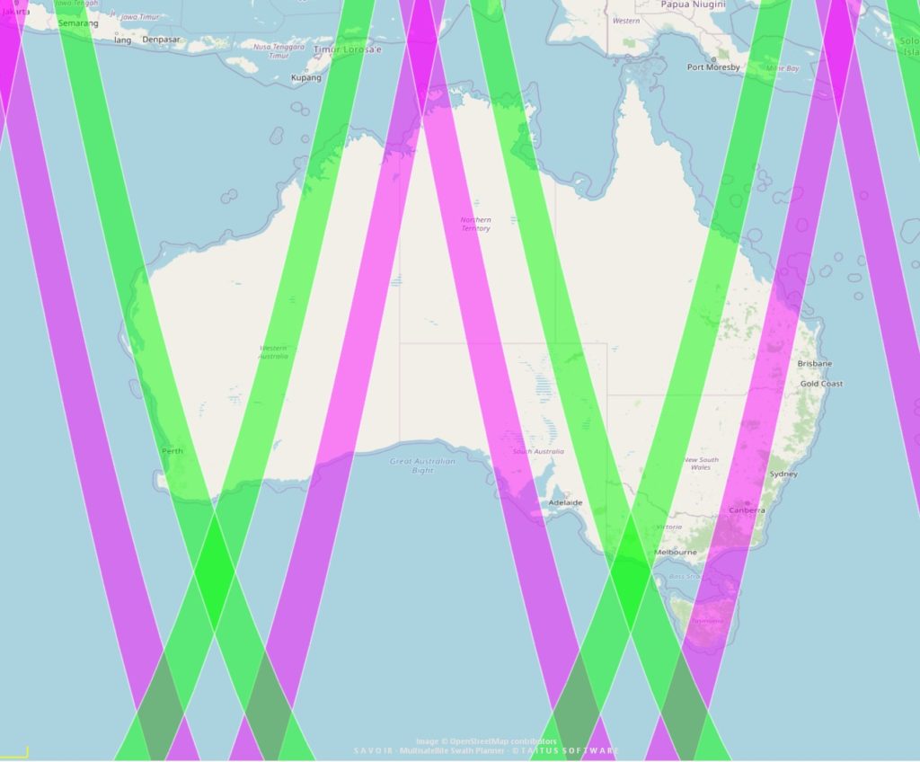
Antenna Pointing
NovaSAR-1 antenna pointing demonstrated with ScanSAR wide 195km swath: Left = Pink, Right = Green
Orbit Parameters
NovaSAR-1 operates in a sun-synchronous orbit at 580km with an LTAN (Local Time of the Ascending Node) of 10:30. The satellite ground track can be seen below. Each orbit shifts to the west by approximately 24.3° of longitude at the equator. There are 15 revolutions a day resulting in 3-4 passes day over Australia.
| Parameter | Value |
| Repeat Cycle | 16 days |
| Revolutions per day | 15 |
| Period (Minutes per orbit) | 97 minutes |
| Revolutions per cycle | 209 |
| Ground track distance at the equator | 192 km |
| Ground track distance over Australia | 138- 88 km |
| Altitude | 583 km |
| Inclination | 97.86 deg |
| LTAN | 10:30 |
| Eccentricity | 0.00165 km |
| Semi Major Axis | 6967 km |
| Satellite Catalog Number/NORAD ID | 43619 |
Repeat Cycle
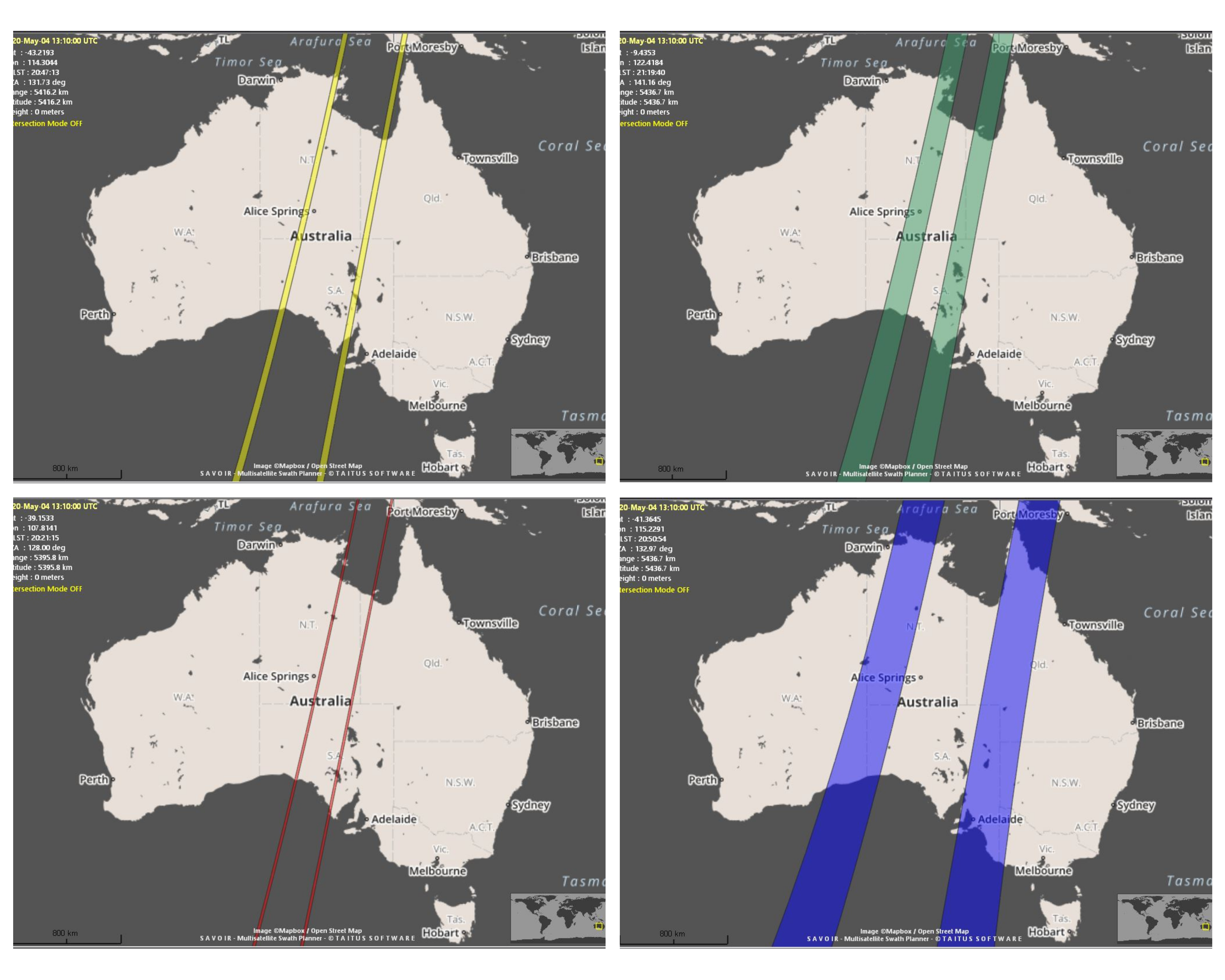
The repeat cycle (for the same mode and look direction) is approximately 16 days. However, NovaSAR-1 does not operate with a fixed orbit but has a slight drift (described above). This means it does not follow a path/row acquisition strategy like other satellites and therefore acquisition parameters over the same area will vary slightly between acquisitions, as shown below.
Due to the orbital shift, opportunities for interferometric measurements are ad-hoc and limited to archive image pairs with a small enough spatial baseline. For a study of this see: IGARSS 2022 – 2022 IEEE International Geoscience and Remote Sensing Symposium | 978-1-6654-2792-0/22/$31.00 ©2022 IEEE | DOI: 10.1109/IGARSS46834.2022.9883695
There is the potential to control the orbit over a short section of the satellite’s total lifetime to provide a demonstration interferometric capability but this would need agreement from all mission partners.
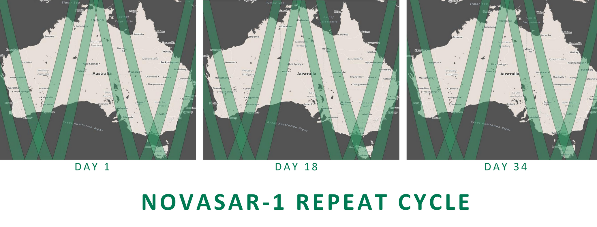
NovaSAR-1 repeat cycle demonstrated with ScanSAR wide 195km swath in Left and Right look directions and Ascending and Descending Pass Directions
Level-0
Level-0 products consist of raw SAR data and are the basis on which all other level products are produced.
Level-0 products cannot be provided to users but are stored in the CSIRO archives so that they can be used to reprocess any level of product while the data is available.
Level-1
Level-1 products are automatically produced by CSIRO using software produced by the SAR payload manufacturer Airbus DS
Level-1 products are provided to users free and open-access without a proprietary period and are available in the following product types:
SAR Products
| Name | Created Using | Processing Applied |
|---|---|---|
| L0 | Raw products | None |
| L1 SLC | L0 products | Single look complex product (in slant range projection) |
| L1 GRD | L1 SLC products | Multi-looked ground detected product (in ground range projection using Earth reference ellipsoid, i.e. no terrain correction applied) |
| Product | Looks | Range | Applicable Mode |
|---|---|---|---|
| SLC | Single Look Complex | Slant Range | Stripmap only |
| SRD | Multi Look Detected | Slant Range | Stripmap only |
| GRD | Multi Look Detected | Ground Range | Stripmap only |
| SCD | Multi Look Detected | Ground Range | ScanSAR only |
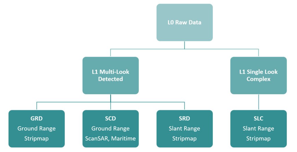
NovaSAR-1 product types
CEOS-ARD Products
CEOS Analysis Ready Data (CEOS-ARD) are ‘satellite data that have been processed to a minimum set of requirements and organised into a form that allows immediate analysis with a minimum of additional user effort and interoperability both through time and with other datasets’.
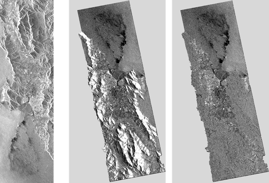
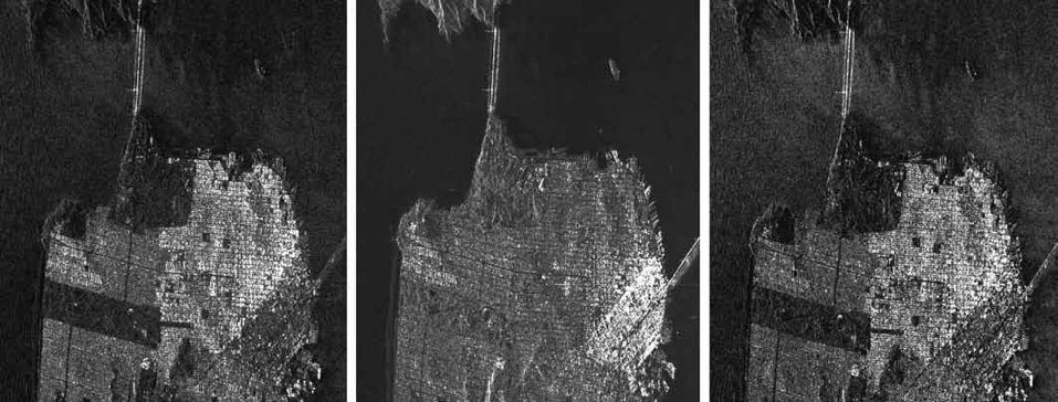
A sample of NovaSAR-1 ARD processing for Acquisition 39919 is shown as follows: HH Source in radar geometry (left), HH Beta0 (middle) and HH Gamma0-RTC (right) in map projection.
The NovaSAR-1 product directory name is of the form:
NovaSAR_sn_AcqID_xxx_date_time_polList
where:
- NovaSAR_sn indicates the platform from which the acquisition was made
- AcqID is the acquisition_ID, a numerical value that increases over time, the CSIRO archive will not contain a full sequence as other mission partners images use the same numbering scheme
- xxx indicates the Product Type and will be can be SLC, GRD, SRD or SCD
- date_time indicates the acquisition start time in the format YYMMDD_hhmmss
- polList indicates the set of polarisations used for the acquisition, this can be single polarisation e.g. _HH or a combination of polarisation e.g. HH_HV
As an example: NovaSAR_01_12737_scd_200706_160034_HH_HV.zip has Acquisition ID 12737 and is an SCD product acquired at 16:00:34 on 06/07/2020 with HH and HV polarisations.
NovaSAR-1 products are distributed in a zip folder and consist of:
- One or more Image Product File(s)
- One or more Quick-Look Image file(s)
- One Metadata File
- One Metadata Stylesheet File
L1 Image Product File
The Image Product file is in GeoTIFF .tif format and contains the image processed to the resolution specified for the imaging mode. Multiple Image Product Files will be present when:
- An image is comprised of multiple polarisations, in this case a file will appear for each polarisation e.g. image_HH.tif, image_HV.tif and image_VV.tif as below
- A single Image Product File would exceed the TIFF format 4 GByte limit. In this case the image is divided into equal slices as below
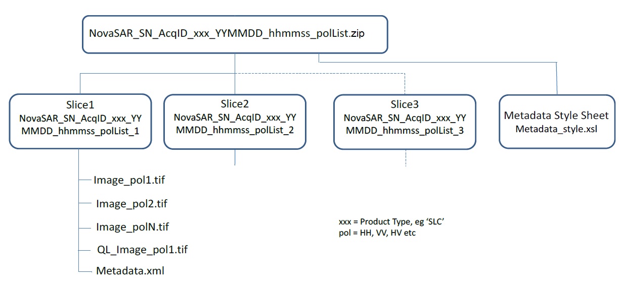
NovaSAR-1 convention for directory names
L1 Quick Look Image File
The Quick-look Image file contains a coarser resolution version of the processed image, always in detected format (ie never complex). The coarser resolution is achieved using an adaptive subdivision process to average neighbouring pixels so that the image size is reduced to around 1K x 1K pixels. It is named QL_image_pol.tif where _pol indicates the polarisation for the Quick-Look image, ie _HH or _HV etc
L1 Metadata File
The Metadata File is named Metadata.xml and logically records full information on SAR data acquisition, image generation and image characteristics. It enables full interpretation of the Image Product File.
A full description of the Metadata Parameters can be found here
L1 Metadata Stylesheet File
The Metadata Stylesheet is named Metadata_style.xsl and provides formatting information for the Metadata file to a compatible web browser (eg Internet Explorer).
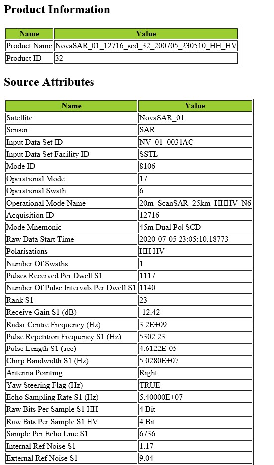
NovaSAR-1 metadata viewed using the stylesheet
CEOS-ARD Metadata
This is a CARD4L NRB PFS Version 5.5 compliant NovaSAR-1 ARD product produced by CSIRO.
CEOS-ARD Naming Conventions
The naming conventions of NovaSAR-1 CARD4L NRB product are as follows:
- CARD4L: CEOS Analysis Ready Data for Land
- NRB: Normalised Radar Backscatter
- PFS: Product Family Specifications
- v5.5: Version number of PFS
- A: Ascending orbit
- D: Descending orbit
- L: Left pointing of antenna
- R: Right pointing of antenna
- QL: Quick Look
CEOS-ARD Product Structure
A sample of NovaSAR-1 ARD product zip file structure is as follows:
- CARD4L_NRB_v5.5_NovaSAR_01_19589_scd_27_210205_142144_VV_HH_HV_D_R.zip:
- Annotation
- Measurement
- Preview
- CARD4L_NRB_N1_product_metadata.xml
- CARD4L_NRB_N1_product_metadata.yaml
- readme.txt
CARD4L_NRB_v5.5_NovaSAR_01_19589_scd_27_210205_142144_VV_HH_HV_D_R.zip/Annotation:
        CARD4L_NRB_v5.5_GammaToSigmaRatio_N1_19589_scd_27_D_R_20210205T142144.tif
        CARD4L_NRB_v5.5_LocalIncidenceAngle_N1_19589_scd_27_D_R_20210205T142144.tif
        CARD4L_NRB_v5.5_Mask_N1_19589_scd_27_D_R_20210205T142144.tif
        CARD4L_NRB_v5.5_ScatteringArea_N1_19589_scd_27_D_R_20210205T142144.tif

CARD4L_NRB_v5.5_NovaSAR_01_19589_scd_27_210205_142144_VV_HH_HV_D_R.zip/Measurement:
        CARD4L_NRB_v5.5_Gamma0_HH_N1_19589_scd_27_D_R_20210205T142144.tif
        CARD4L_NRB_v5.5_Gamma0_HV_N1_19589_scd_27_D_R_20210205T142144.tif
        CARD4L_NRB_v5.5_Gamma0_VV_N1_19589_scd_27_D_R_20210205T142144.tif

CARD4L_NRB_v5.5_NovaSAR_01_19589_scd_27_210205_142144_VV_HH_HV_D_R.zip/Preview:
        Map_Overlay_NovaSAR_01_19589_scd_27_210205_142144_VV_HH_HV_D_R.bmp
        Map_Overlay_NovaSAR_01_19589_scd_27_210205_142144_VV_HH_HV_D_R.kml
        QL_image_HH.tif
        QL_image_HV.tif
QL_image_VV.tifAmbiguities
Ambiguities are false targets that appear in images. Azimuth ambiguities are due to aliasing caused by the sampling of the Doppler spectrum at intervals using a pulsed system. Range ambiguities are caused by echoes received from earlier or later pulses arriving back to the antenna at the same time as the desired echo. The ambiguity ratio is the degree to which ambiguities are suppressed. Acceptable ambiguity ratios are of the order of -15dB to -20dB which is achieved by NovaSAR (except in the case of Maritime mode which is designed to be deliberately ambiguous in azimuth in order to maximise the swath).
Speckle
Speckle is reduced by the use of multi-looking. The full synthetic aperture is split into several sub-apertures in time and/or frequency, each representing an independent ‘look’ of the identical scene. The incoherent summing of these looks forms an image with reduced speckle and degraded spatial resolution.
Maritime Mode
Maritime Mode is not intended to be used to generate images. It is a low radar pulse frequency mode that will generate a 2-D dataset with a pattern of ambiguous responses for targets with suitable radar cross-section. The low pulse frequency enables a wider swath than can be achieved with imaging modes at the expense of multiple ambiguous artefacts for each target. It is anticipated that this mode is used for ship detection in the open sea.
Geolocation Accuracy
NovaSAR-1 Images can use 2 sources of Orbit Data (Metadata tag: OrbitData) which it uses for geolocation. The first choice is the GPS data recorded on the satellite at the time of acquisition, which produces the most accurate results. If the GPS data is not available the TLE data is used which has lower accuracy.
Time Stamp
In some cases, the geolocation of an image may be incorrect in the along-track direction (North or South) by around 6.5-7km. This is due to a known issue caused by time rounding to the wrong nearest second and can be easily rectified by CCEO staff. Please complete this form and we will generate a new version of the image.
Image/Product Size
All our products are produced as single image product files unless they exceed the TIFF format 4 GByte limit. If these files are too large for you to download or analyse, please contact us to discuss manual processing to a more manageable size.
Suspect Calibration
NovaSAR-1 images are given a Calibration Status (Metadata tag: CalibrationStatus) of SUSPECT for one of 2 reasons:
- If a TLE file is used to generate the product and the TLE data is not within 5 days of the timestamping of payload raw data.
- If the payload internal calibration data embedded within the payload raw data suggests that SAR focusing will not be optimal and that resultant pixels will have degraded brightness.
Calibration of NovaSAR-1 was undertaken by SSTL during the spacecraft commissioning and involved assessment of the following features against their expected values:
- Reference chirp
- IRF Sidelobe symmetry
- IRF PSLR
- Resolution
- Radiometric stability
- Radiometric correction across swath
- Sensitivity
- Geolocation
- Swath
- Polarimetric
- Pointing knowledge
These measurements are repeated on an annual basis throughout the mission lifetime to identify any variation in performance.
Method:
Radiometric/geometric calibration using passive targets including:
- Rain forest (wide-area homogenous distributed targets)
- Calm water, salt flats and airport runways (low backscatter dark targets)
- Corner reflectors (known radar cross-section point targets):
- Guildford, UK / SSTL – 1.5m trihedral corner reflector, boresight varied
- Great Baddow, UK / BAE Systems – 2.5m trihedral corner reflector, boresight varied
- Rosmand, CA / JPL – 2.5m and 4.8m trihedral corner reflectors, fixed boresight (used for measurements not requiring known radar cross-section)
Results
- Radiometric stability
- standard deviation of 0.41 dB
- the metadata field “RadiometricScaling” indicates whether the image has be generated with beta nought, sigma nought or gamma nought scaling
- the metadata “CalibrationConstant” field can be used to convert the pixel integer value into a scaled value: Scaled pixel value = (pixel amplitude)^2 / CalibrationConstant
- Geometric accuracy
- the mission planning software uses an estimate of height (above the WGS84 earth ellipsoid model) at the middle of the image to plan the image. This height is written into payload configuration and the payload writes it into the raw data
- the image processing software uses platform orbit information, pulse timing, the WGS84 ellipsoid model of the earth and the height written into raw data to georeferenced images
- the height used for georeferencing is written into the metadata field “MeanTerrainHeight”
- for accurate geolocation of all points another tool must be used to perform terrain correction on the IFP output
- mission requirement for geolocation error is better than 50m (3σ) with respect to the reference Earth ellipsoid (without Ground Control Points and terrain correction).
- when geometric correction is applied to the data to account for the difference between the ellipsoid height used to generate the level 1 product and the actual terrain height, the geolocation requirement is easily achieved and is typically <10 m
NovaSAR-1 Data can be opened and processed using the following software:
Commercial
- GAMMA produced by Gamma Remote Sensing – NovaSAR-1 Readers are available in Gamma
- SAR Solutions produced by NV5 Geospatial
Open-Access
European Space Agency SNAP toolbox.
There is a NovaSAR-1 Product Reader available as a SNAP Extension which can be installed via (Tools->Plugins->Available Plugins). It can also be manually downloaded here.
However, not all utilities are currently operational for NovaSAR-1 data, e.g. Geometric Terrain Correction, therefore compatibility of the data with this platform is limited at this time. Any further updates will be recorded here.
Instructions for installing the ESA SNAP toolbox and NovaSAR-1 reader plug-in
- Install the SNAP Sentinel-1 toolbox using the links above
- Install the NovaSAR-1 reader using:
Tools > Plugins > Available Plugins > NovaSAR Product Reader - Check the plugin has installed by going to:
File > Import > SAR Sensors
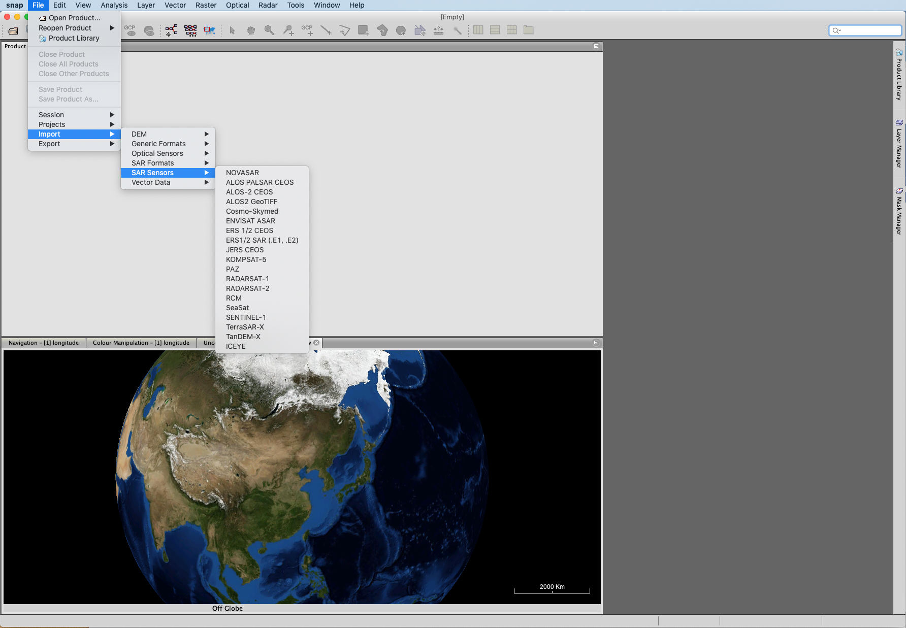
SNAP NovaSAR Product Reader Installation
More information on how to use NovaSAR-1 data in SNAP is available here