Introduction
This tutorial provides step by step instructions on how to use Workspace for the purposes of visualising 3D data. After following the tutorial, users will be able to:
- Create a basic scene composed of:
- Create a display widget to view and interact with their scene
These processes will often be all that is required to quickly visualize 3D data being processed in the workflow.
A sample workflow has been provided for this tutorial.
Prerequisites
It is expected that users following this tutorial have an understanding of Workspace basics explained in the tutorial Hello Workspace!.
- Note
- In order to make use of the rendering plugin, users will also need to have a machine that has reasonably up-to-date graphics hardware (that supports OpenGL 2.1 or later). If your system is not capable of hardware accelerated rendering, an error message will be reported in the Workspace log, showing that the rendering plugin has not been loaded.
1 Creating a basic scene
To create a basic scene, we need first to understand some concepts core to visualisation with Workspace:
- The MeshModel data type
- The Scene data type
1.1 The MeshModel data type
A MeshModel is used to represent a model comprised of a set of Nodes (aka vertices), and a set of Elements (e.g. triangles) which connect the nodes in order to form a 3-dimensional structure. The supported element types are as follows:
- Lines (known as Segments)
- Triangles or Quadrilaterals (known as Shells)
- Tetrahedrons or Hexahedrons (known as Volumes)
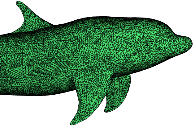
An example of a model comprised of a number of shells
In addition to their standard geometric properties, both Nodes and Elements can have an arbitrary number of scalar or vector states (floating point or integer) associated with them, such as texture coordinates or physical properties like Velocity or Kinetic Energy.
Most of the rendering operations in Workspace have inputs and outputs corresponding to the MeshModel data type, so although Workspace supports any user-defined data types, in order to take advantage of the out-of-the-box rendering capabilities, all data of this nature must be processed in the form of the MeshModel data structure.
1.2 The Scene data type
A Scene represents an area in 3D space, which can contain models, lights, cameras and other entities. Anything that can be added to a scene is known as a "SceneItem". In order to visualise a model and control its appearance, it must be placed into a scene.
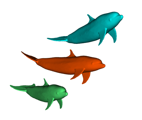
An example of a scene containing multiple models
1.3 Creating the scene
In this tutorial, we are going to build a scene comprised of a small number of objects:
- A 3D model
- A light
- A camera
We are then going to visualise and interact with the scene.
1.3.1. Create a model reader
The first thing we are going to need is a model, which we're going to read from a file:
- Select
File > New workflow from the menu. This will create a new blank workflow.
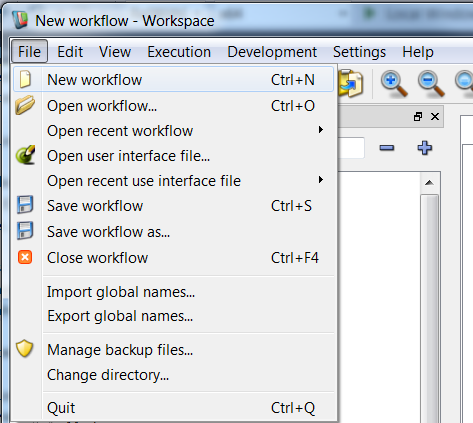
Create a new workflow
- In the Operation Catalogue, find the
FileIO > SelectableMeshReader operation, and drag it from the catalogue onto the workspace canvas. This will create a SelectableMeshReader operation, which is used to read mesh data in a variety of formats.
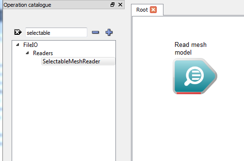
Create a SelectableMeshReader operation
- Note
- The SelectableMeshReader operation has its label set to "Read mesh model" by default.
- Click on the operation to select it. This will display all of its inputs and outputs in the Operation editor dock.
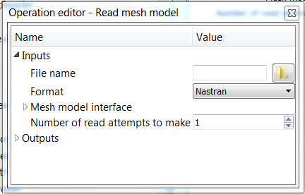
Selecting the operation
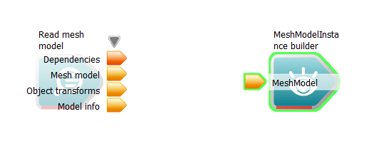
We can see that this operation has four inputs; a file name, a format, a mesh model interface and number of read attempts to make. If we expand the outputs menu by clicking on the arrow next to it, we can see that it has two outputs; a mesh model and a set of object transforms.
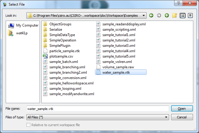
- Next to the 'File name' input in the Operation editor dock, click on the Browse (folder) button. In the displayed file selection dialog, navigate to the
doc/Workspace/Examples folder, select the water_sample.vtk file and click Select. The filename input of the operation will now be set.
Open File dialog
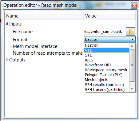
- We now need to specify the format which we want to use to interpret the file. To do this, select VTK From the drop-down menu shown for the Format input in the Operation editor dock.
Selecting VTK as the reader type
1.3.2. Create a model instance
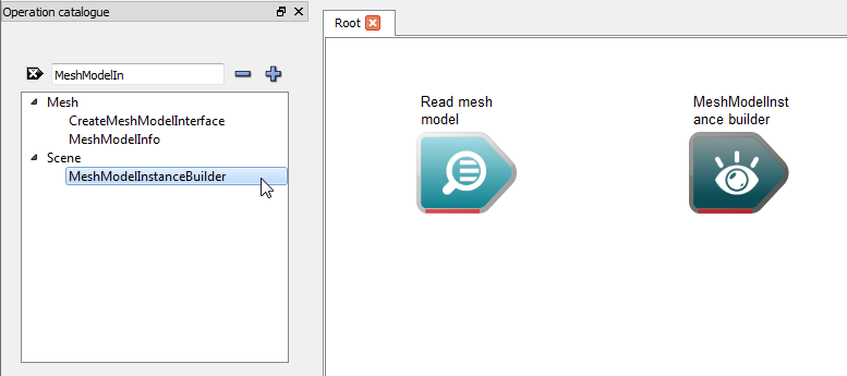
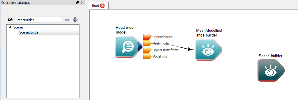
- Now we have a reader operation which reads our data file and creates a MeshModel for us. The next step is to create an 'instance' of this MeshModel in our scene so that we can customise its appearance. To do this, we add a MeshModelInstanceBuilder to our workflow. Navigate to the
Scene section of the Operation catalogue and drag the MeshModelInstanceBuilder onto the workspace canvas.
Creating a MeshModelInstance
- We now need to connect our Reader to our MeshModelInstanceBuilder so that it has some data. To do this, click and drag the Mesh output of the SelectableMeshReader to the MeshModel input of the MeshModelInstance builder.
- Note
- For more information on the MeshModelInstanceBuilder, please see the advanced rendering tutorial.
- You will need to enter a Mesh Model ID in the Operation Editor - you can set this to numeric value of 1.
The workflow after adding the MeshModelInstanceBuilder
1.3.3. Create the scene builder
- Now we need to add our MeshModelInstance to a Scene so that we can visualise it. To do this, navigate to the
Scene section of the Operation catalogue and drag the SceneBuilder operation onto the workspace canvas.
Create a SceneBuilder operation
- To connect the MeshModelInstance to the SceneBuilder, click and drag the Mesh model instance output of the MeshModelInstance onto the Scene items array input of the SceneBuilder.
- Note
- If you look carefully, you will see that the data type of the Scene items input is actually an array of SceneItem. SceneItem is a base class for all types that can be added as a child of a Transform. The Transform is a type of SceneItem which represents a linear transform applied to one or more scene items; for example, a rotation applied to a MeshModelInstance. The MeshModelInstanceBuilder implicitly creates a transform object containing the MeshModelInstance, allowing you to transform it without having to create an extra TransformBuilder operation.
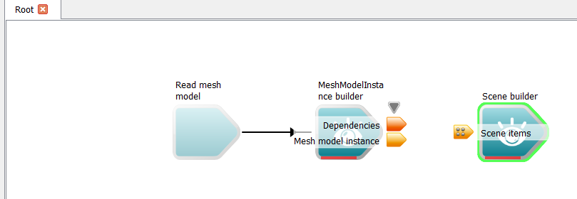
The workflow after adding the SceneBuilder
1.3.4. Create a camera and light
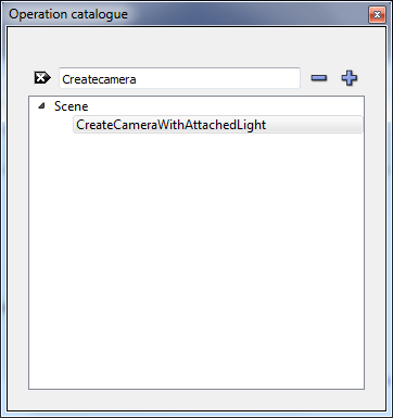
- We cannot visualise our model without a viewport into the scene, nor can we make sense of a 3D scene without illuminating its contents. To control these elements of our scene, we need to add two more operations to our workflow; a Camera and a Light. Different types of lights and cameras exist in Workspace, but the simplest way to add them to a scene is to use the CreateCameraWithAttachedLight operation. To do this, find the CreateCameraWithAttachedLight operation under the
Scene section of the Operation catalogue, and drag it onto the workspace canvas.
Creating a Camera and Light
- The Camera and Light are both children of a parent Transform which we need to add to our Scene. To do this, drag the Transform output of our newly created operation to the Scene items array input of the Scene builder.
- Note
- This Operation is actually a workflow on its own - double click the operation and you will be able to see the sub-operations that it is comprised of.
To verify our steps, we need to perform one last action: right click on the Scene output of the SceneBuilder and select the Create workspace output option. After this, click the Execute button. All operations should execute with no errors. The workflow should now look similar to the image below:
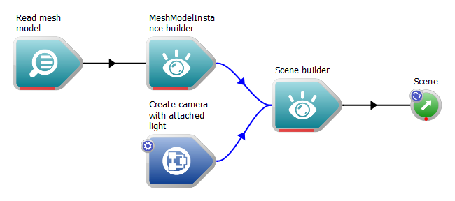
The completed workflow
Step 2: Viewing our scene
In order to visualise the scene, we need a widget which is capable of displaying its contents. Workspace provides such a widget out of the box; it is known as the "WSGLWidget" (short for "Workspace OpenGL Widget"). In order to visualise our scene, all we need to do is:
- Right click on the Scene output of our SceneBuilder operation and select the Display with WSGLWidget option. This will create a new OpenGL rendering window.
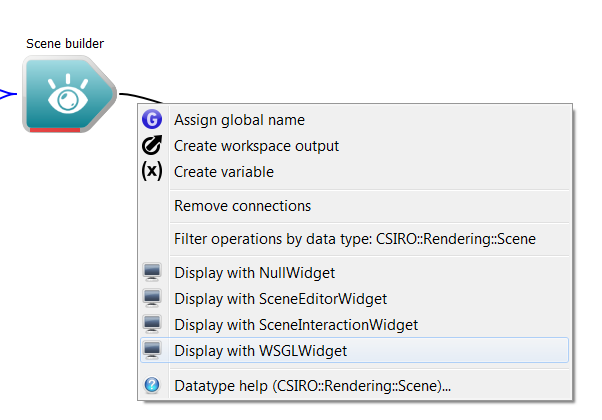
Creating a WSGLWidget
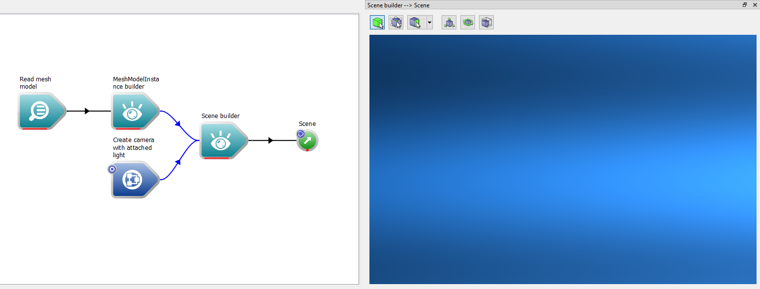
The Docked WSGLWidget displaying a Scene
- Make sure workflow is executing
Initially, the model may not be visible, as the camera's default settings may not match up with the scale of the scene and its contents. To resolve this problem:
- Right-click anywhere in the WSGLWidget and select the Fit view to scene button. This will automatically move the camera so that it fits to the scene's contents.
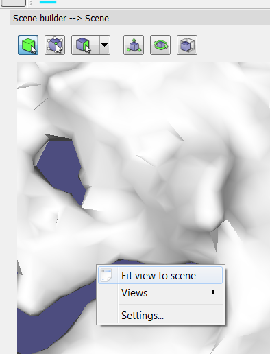
Selecting the Fit view to scene option
The modified (and floating) WSGLWidget after Fit view to scene
- Note
- Make sure that the workflow is executing when trying to auto fit. If the workflow is not executing, the WSGLWidget will display nothing.
Interacting with the scene
Once the widget is created, interacting with the scene is done by using a number of keyboard / mouse controls while the widget is selected. The commands are used to manipulate the camera, provided that it is set to interactive (enabled by default). By default, the controls are as follows:
| Action | Control |
| Rotate camera | CTRL + Left Mouse Button |
| Pan camera | SHIFT + Left Mouse Button |
| Zoom camera (adjust field of view) | Mouse Scroll Wheel forward / back |
| Dolly camera (move forward / back) | SHIFT + Mouse Scroll Wheel forward / back |
| Move near clipping plane | CONTROL + Mouse Scroll Wheel forward / back |
| Move far clipping plane | CONTROL + SHIFT + Mouse Scroll Wheel forward / back |
Summary
That concludes the first rendering tutorial. We have now learned how to:
- Create a simple scene for the purposes of visualisation
- Read model data from file
- Create simple lights and cameras
- Use a WSGLWidget to interact with our scene
A complete sample workflow for this tutorial can be found here.
Next Steps
A number of other tutorials are available to provide examples of how to use the more advanced features of Workspace's rendering capabilities, such as filtering, glyphing and off-screen rendering:
- Changing a model's appearance
- Glyphing a model
- Instancing and applying linear transforms to models
- Off-screen rendering