Manipulation Benchmark
Validate your simulation environments using a benchmark comprised of real-world manipulation tasks
– Benchmark Description
The Robotics and Autonomous Systems Group in collaboration with the Queensland University of Technology has created a benchmark for simulated manipulation. The benchmark allows comparison of simulators to the real world.
To request a transcript please contact us.
Below we present a benchmark alongside a real-world dataset, we anticipate that it will be useful for researchers and developers working on advancing manipulation, sim2real, physics engines and simulators. The benchmark will allow users to validate their current research environments and allow for comparison between simulation environments, promoting robust simulated solutions that transfer well to real-world platforms.
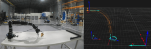
Kinova robotic manipulator performing a task alongside the motion capture recording of the task.
– How to get started
You can run an example using our baseline code, as per below:
- Clone the git repository.
- Run the python code.
- Use the performance metric script to generate metrics comparing simulation to the Dataset.
- Submit your results via the Results Submission Form to be ranked via the Results Ranking Page.
- Now benchmark your simulation environment!
– Benchmark Details
Simulators
You can benchmark any simulator! Follow the protocol description (found here) for each task to build the same scene.
If your simulator supports the importation of URDF files then you will be able to use the one provided, if not then you are able to assemble the robot from the provided STL meshes.
For objects the robot interacts with you can either use primitive shapes if the simulator supports this or import meshes of the shape. We provide meshes of these shapes for you.
The only restriction on your simulation is the control of the robot arm. The controller for the robot arm is a velocity controller with predefined positions reached using a proportional controller. All other parameters are able to be exploited to improve the simulators performance, just remember to report settings you changed when submitting your results!
Dataset
See the Dataset page for dataset data.
Comparison Metrics
We provide a script (/MetricScript/performance_metrics.py) to calculate the results for you as long as you follow the formatting guide specified in the task protocols.
The metrics we use to assess performance are as follows:
- Euclidean – The 3D Euclidean distance error between the real and simulated manipulators averaged across the number of data points.
- Rotational – The rotational error is measured as the Geodesic on the unit sphere.
- Pose – An error metric that accounts for both translational and rotational error.
- Velocity – The error between real and simulated velocities calculated as the change between positions. We also report the maximum simulated velocity.
- Acceleration – The absolute acceleration error calculated as the rate of change between positions. We also report the maximum acceleration and maximum deceleration.
- Torque – The absolute difference between simulated and real joint torques for the 6 joints of the Kinova Mico2. We also report the minimum and maximum simulated torque required throughout the task.
- Contact Force – The force error between the three axis of measurement recorded by the FT300 sensor and the equivalent joint in simulation. We also report the maximum contact force.
- Contact Moment – The moment error between the three axis of measurement recorded by the FT300 sensor and the equivalent joint in simulation. We also report the maximum contact moment.
If the scene also includes object/s for interaction then the following metrics are also required:
- Object Moving Time – The amount of time that the object is not stationary.
- Object Velocity – During non-stationary periods what is the maximum and average velocity of the object.
- Object Acceleration – During non-stationary periods what is the maximum acceleration, maximum deceleration and absolute average acceleration of the object.
- Mahalanobis Distance – The Mahalanobis distance of the translation and another distance for the rotation of the object. This is measured between the real-world data distribution from the 20 repeats and the deterministic result from simulation.
Tasks
The Dataset page includes videos of the task being performed and the task protocols.
Objects, Meshes and Robot Description
Plastic files were printed using Stratasys ASA plastic. Wooden objects were machined from white mahogany wood.
| Shape and Description | Image | Links |
|---|---|---|
| URDF File – The Unified Robot Description Format file is an edited version of the URDF of the m1n6s300 available from the Kinova ROS repository. Most robotic simulators allow for URDF files to be imported natively or through scripts or plugins. The edits to the file add the Robotiq FT300 and the required mounts found below. | 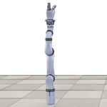 |
URDF File:
/MeshShapes/Kinova_description
Meshes: /MeshShapes/
|
| Cube Plastic – A plastic cube weighing 0.07Kgs. The cube contains marker positioning indentations on two sides to allow for easy marker placement in the Motion Capture system. | 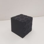 |
|
| Cube Wood – A wooden cube weighing 0.46Kgs. | 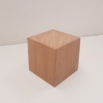 |
|
| Cylinder Plastic – A plastic cylinder weighing 0.12Kgs. The cylinder has marker positioning indentations on one face to allow for easy marker placement in the Motion Capture system. |  |
|
| Cylinder Wood – A wooden cylinder weighing 0.78Kgs. | 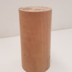 |
|
| Cone Plastic – A plastic cone weighing 0.04Kgs. The cylinder has marker positioning indentations on its one face to allow for easy marker placement in the Motion Capture system. | 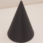 |
|
| Cone Wood – A wooden cone weighing 0.17Kgs. | 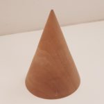 |
|
| Cuboid Plastic – A plastic cuboid weighing 0.14Kgs. The cuboid has marker positioning indentations on two sides to allow for easy marker placement in the Motion Capture system. | 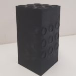 |
|
| Cuboid Wood – A wooden cuboid weighing 0.85Kgs. | 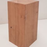 |
|
| Sensor Mount – The sensor mount is fastened between the Kinov Mico2 6th actuator and the Robotiq FT300 sensor. | 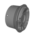 |
|
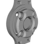
| Gripper Mount – The gripper mount is attached to the FT300 sensor and the Kinova KG-3 three fingered gripper. |
 |
Publications
Below is a list of citations and links to publications describing the dataset (ours) and publications that use the benchmark or dataset.
For more information contact Jack Collins at Jack.Collins@data61.csiro.au
[jetpack_subscription_form title=”Subscribe to our News via Email” subscribe_text=”Enter your email address to subscribe and receive notifications of new posts by email.”]